Watch Now: Understanding Impedance – Resistance, Inductive Reactance, and Capacitive Reactance!
What is Impedance?
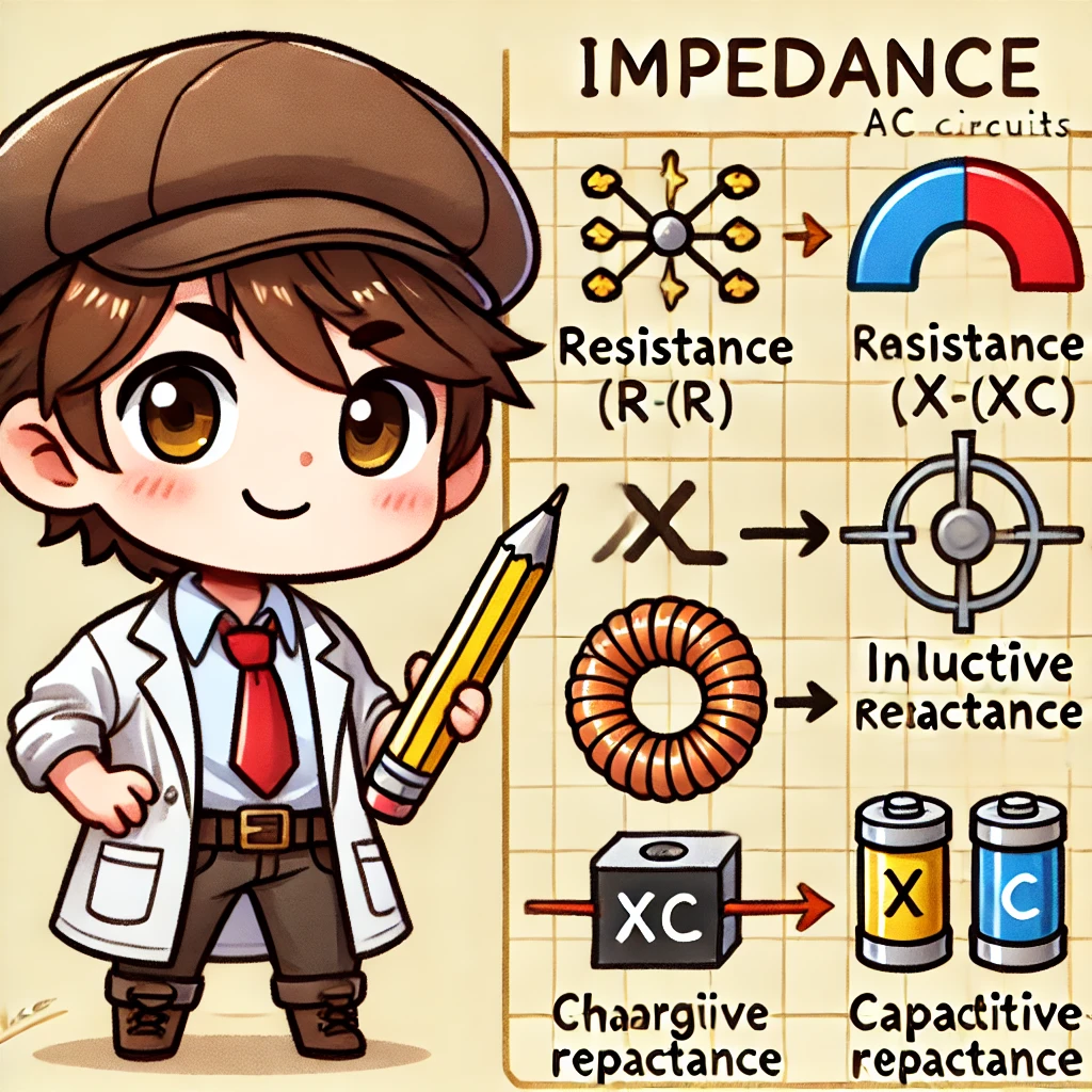
Impedance is a fundamental concept in AC circuits, determining how current flows through a circuit. Unlike resistance in DC circuits, impedance consists of three key components: resistance (R), inductive reactance (XL), and capacitive reactance (XC). Understanding these elements helps in designing efficient electronic and power systems.
This article explores the characteristics, formulas, and applications of these three impedance components in electrical circuits.
Resistance (R) – The Fundamental Current Limiter
Characteristics of Resistance
Resistance is an element that dissipates energy, converting some of it into heat as current passes through. According to Ohm’s Law, resistance is calculated as: V=IR
Where:
- V = Voltage (Volt)
- I = Current (Ampere)
- R = Resistance (Ohm, Ω)
Applications of Resistance
- Current Limiting: Protects components from excessive current.
- Voltage Division: Helps distribute voltage across circuit elements.
- Heating Applications: Used in electric heaters, irons, and other devices that generate heat.
Inductive Reactance (XL) – The Role of Inductors in AC Circuits
Characteristics of Inductive Reactance
Inductive reactance is the property of an inductor that resists changes in AC current. When AC flows through an inductor, it creates a varying magnetic field, generating an opposing voltage (electromotive force, EMF). The formula for inductive reactance is: XL=2πfL
Where:
- XL = Inductive reactance (Ω)
- f = Frequency (Hz)
- L = Inductance (Henry, H)
Applications of Inductive Reactance
- Filtering Circuits: Removes high-frequency noise (e.g., power supply filters).
- Electric Motors and Transformers: Operates based on electromagnetic properties.
- Radio and Communication Equipment: Adjusts signal frequencies in high-frequency circuits.
Capacitive Reactance (XC) – The Role of Capacitors in AC Circuits
Characteristics of Capacitive Reactance
Capacitive reactance is the ability of a capacitor to oppose AC flow. When AC voltage is applied, capacitors alternately charge and discharge, affecting current flow. The formula for capacitive reactance is: XC = 1 / (2πfC)
Where:
- XC = Capacitive reactance (Ω)
- f = Frequency (Hz)
- C = Capacitance (Farad, F)
Applications of Capacitive Reactance
- Signal Filtering: Blocks DC and allows AC (e.g., coupling capacitors).
- Power Supply Filtering: Stabilizes voltage fluctuations and improves quality.
- Wireless Communication: Adjusts circuit frequency response for signal processing.
By understanding how resistance, inductive reactance, and capacitive reactance work together, engineers and hobbyists can design more efficient AC circuits for various applications.

Impedance Calculation and Phase Relationship
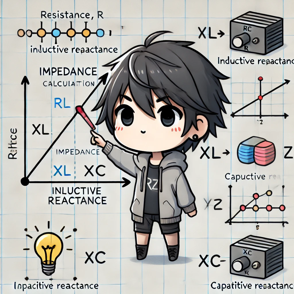
Impedance (Z) is composed of resistance (R), inductive reactance (XL), and capacitive reactance (XC). It is calculated as a vector sum using the formula: Z=√(R2+(XL−XC)2)
Phase Relationship in AC Circuits
- If XL > XC → The circuit exhibits inductive characteristics, where current lags behind voltage.
- If XC > XL → The circuit exhibits capacitive characteristics, where current leads voltage.
- If XL = XC → The circuit reaches resonance, a critical condition in oscillating circuits and wireless communication systems.
Understanding impedance and its phase behavior is essential for designing efficient AC circuits, improving power transmission, and optimizing signal processing in electronic systems.

Simple Experiment: Testing Impedance Effects in AC Circuits
This experiment demonstrates how resistance, inductive reactance, and capacitive reactance influence AC circuits at different frequencies.
📌 Materials Required
- Resistor (1kΩ)
- Inductor (10mH)
- Capacitor (100μF)
- Function Generator (to generate AC signals)
- Oscilloscope (to observe voltage and current changes)
📌 Procedure
- Testing Resistance:
- Connect the resistor in an AC circuit.
- Measure the voltage and current response to confirm that resistance remains constant regardless of frequency.
- Testing Inductance:
- Connect the inductor and gradually increase the frequency.
- Observe how inductive reactance (XL) increases with frequency, making it harder for current to flow.
- Testing Capacitance:
- Connect the capacitor and adjust the frequency.
- Note that capacitive reactance (XC) decreases as frequency increases, allowing more current to pass.
🔎 Results & Observations
- Resistance remains unchanged and follows Ohm’s Law.
- Inductive reactance increases with frequency, restricting current flow.
- Capacitive reactance decreases with frequency, permitting greater current flow.
This experiment provides a hands-on understanding of impedance components and how they affect AC circuits, particularly in signal processing, power regulation, and communication systems.

Summary & Further Reading
Impedance is a fundamental concept in AC circuits, composed of resistance, inductive reactance, and capacitive reactance. These three factors determine how a circuit interacts with voltage and current. Understanding their properties allows us to design efficient filters, power circuits, and wireless communication systems, enhancing the performance and efficiency of electronic devices.
📌 Further Reading
🔹 [Resistors: Functions, Types, and Applications You Need to Know]
Learn the fundamentals of resistance, its role in power dissipation, and voltage division applications.
🔹 [Inductance Basics: Understanding Its Role in Power and Wireless Tech]
Discover how inductors store magnetic energy and play a crucial role in voltage regulation, filtering, and wireless power transfer.
🔹 [Capacitors in Action: How They Store and Release Energy] (Coming Soon)
Explore capacitor charging and discharging properties and their use in signal processing and power filtering.
🔹 [How to Calculate Impedance in AC Circuits] (Coming Soon)
Master impedance calculations and learn how to optimize circuit performance with resistors, inductors, and capacitors.


